Challenges
- MIC corrosion
Benefits
- Completed within timeframe and budget
- ICR supplied all bespoke equipment and personnel
Scope
Our customer identified corrosion-related issues aboard its North Sea platform. Found in a P-D flowline, the customer believed this was caused by microbiologically influenced corrosion (MIC) but unfortunately had no method to monitor sessile populations to confirm their theory.
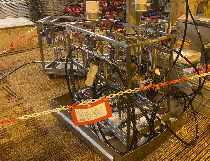
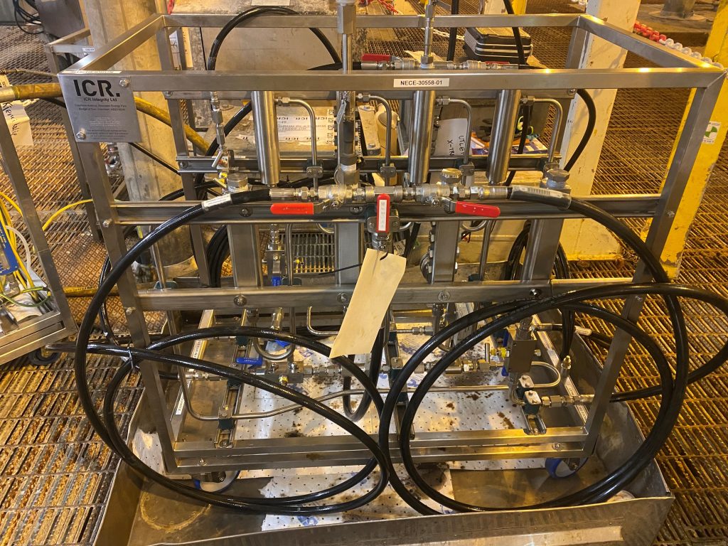
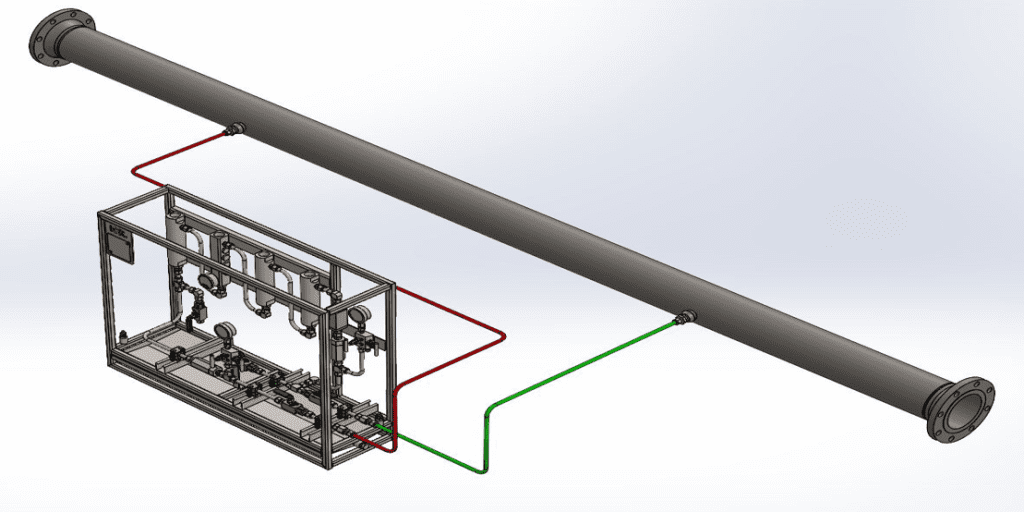
The client, a multinational energy company, requested ICR to design two units – one injecting biocide and the other allowing process fluid to flow through it without biocide – in addition to a chemical injection pump. The goal of this project was to test whether there was a high corrosion rate in the unit without biocide, thereby proving MIC issues.
Collaborating with one of the world’s leading specialty chemical companies, ICR quickly mobilised to the site to assess the risk of MIC and biocide efficiency through sidestreams trials.
Solution
Our Corrosion Management Team conducted a comprehensive biocide trial, including a pre-survey visit to the client’s North Sea platform. The trial was carried out in two phases to ensure comparative data. ICR provided a full trial solution, supplying all necessary equipment and personnel to execute the project.
The full scope of the project included:
- Supply and installation of a dual sidestream unit.
- Provision of a chemical injection unit (CIU) with associated ancillaries.
- Deployment of data logging units for monitoring.
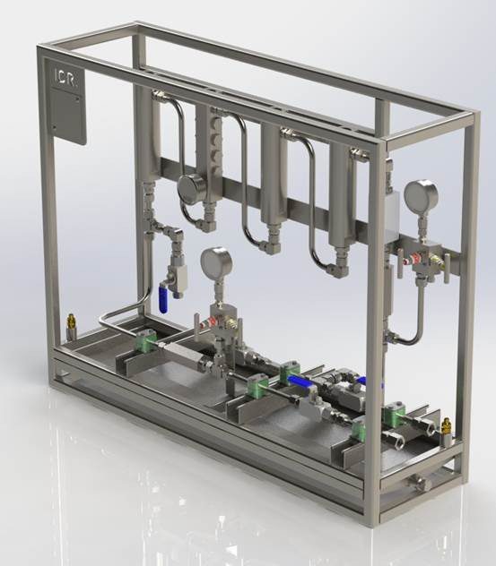
The bespoke sidestream unit was designed and built with the following specifications and pressure-tested in-house to 99 bar, with all components rated to 3,000 psi:
- Flowmeters to ensure matching flow rates in both the non-biocide and biocide sections.
- Double Block and Bleed (DBB) assembly on either side, plus a non-return check valve.
- Ports for periodic sessile MIC analysis, flush disc corrosion coupon installation, a high-sensitivity probe with data logger.
The CIU included:
- Two Williams Milton Roy “V” Series Chemical Metering Pumps.
- Suction, air, and discharge manifolds made of 316SS, with isolation valves, filters, regulators, and relief valves.
- Equipment certification and testing to ensure reliability.
Result
ICR successfully executed the sidestream biocide trial, demonstrating that the corrosion rate was lower in the sidestream unit with biocide injection compared to the unit without.
Our comprehensive approach assessed the integrity and reliability of the P-D flowline and mitigated potential risks associated with MIC.
The project was completed within the required timeframe and budget, showcasing ICR’s capability to design and deliver bespoke equipment.
For more information on ICR’s corrosion monitoring services, click here.
Project gallery
Date: July 2022
Client: Petrofac
Location: Southern North Sea
Client challenge
Petrofac, a leading international service provider to the energy industry, faced issues with injecting chemicals at the optimal rate into their unmanned platform. They needed to inject scale and corrosion inhibitors into their production and gas export flowlines respectively to create atomisation. However, they were experiencing ongoing blockage problems with the incumbent injection devices which needed to be replaced. As a result, Petrofac consulted our corrosion monitoring team to advice on a suitable modification to replace the existing injection devices and avoid prolonged shutdowns with escalating costs. Failure to accurately inject the chemicals would result in inadequate corrosion control, a threat to plant integrity and personnel safety, and potentially poor-quality gas being exported rendering it unsellable.
What we did
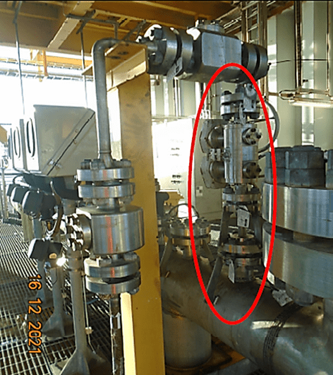
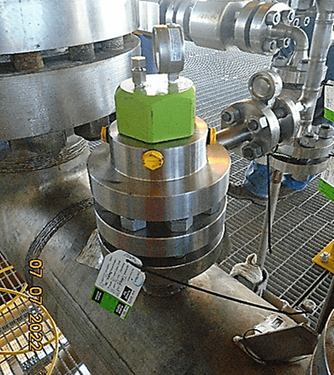
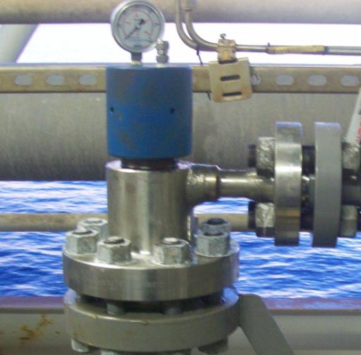
Blockages typically necessitate a shutdown. Our team carried out an initial survey to identify the existing flanged connection specifications, then we recommended the current set up is replaced with RTJ flanged hydraulic chemical injection access fittings with flanged side tee. This will enable nozzle replacement online with the specialist retriever tool.
Results
We successfully guaranteed subsequent blockages will no longer require platform shutting down for replacement saving on costs.
As a result of our work, the chemical injection was more controlled, resulting in a better quality of gas.
Scope
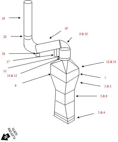
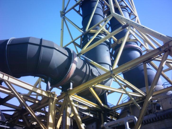
As a result of an ongoing asset life extension study the client had a concern regarding the condition of exhaust stacks located on a 25 year old offshore production platform. The main concern related to potential cracking/hot spots within the exhausts which may in turn be causing temperature anomalies on the surrounding support structure.
Solution
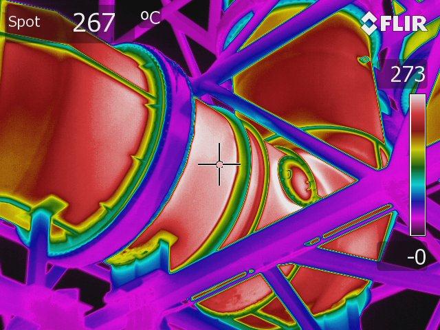
Thermographic and digital images were taken at various points identified around the exhausts to deliver as much information as possible, relating to their overall condition, and report on any identified temperature anomalies located within the surrounding support structure.
The location of the exhaust stacks in question required detailed discussion and agreement with the client on the whereabouts of suitable and safe areas where ICR’s trained Thermographer could take optimum and concise images from. An initial site survey of the area to be inspected was undertaken by a multi-skilled ICR Technician during a routine corrosion monitoring scope of work some months previously.
This site survey was used as basis for discussion and an agreement was reached upon suitable safe locations for the inspection to take place. These included deck levels immediately adjacent to the exhausts and the platform helideck. It was agreed that no additional scaffold construction would be required for the inspection.
Utilising a state of the art infrared thermography camera, the technician carried out the inspection during normal operation of the associated turbine units. Both digital and infrared images were taken of the exhaust at each pre-agreed inspection location and these were presented to the client in a detailed report format.
Results & Benefits
- Inspection showed that the carbon steel exhaust ducting appeared to be in good condition with no signs of cracking or porosity. The flexible flanged area on the horizontal section of stack was found to be in poor condition.
- The structural support beams were also found to be in good condition with heat sources discovered on the section closest to the stacks. This is thought to be due to coating deterioration.
Scope
We were requested by an Oil and Gas Operator to service a number of chemical injection locations throughout the production system on one of its assets during a routine platform shutdown. The majority of these locations had limited service history and ICR had not previously been requested to service these.
At each location the scope of work was to inspect and clean the injection assembly, replace the injection nozzle and renew all pressure retaining seals.
Solution
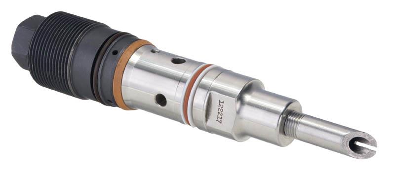
On retrieval of one of the devices the injection assembly was found to be detached from the carrier plug. It is believed this may have happened upon initial installation with the injection nut becoming caught on a weld impingement. As a result it is suspected that the chemical was not being injected at the desired rate / dispersed efficiently.
ICR removed the weld impingement, changed out the chemical injection nut and installed a new injection assembly.
Results & Benefits
- With the injection assembly now installed correctly and functioning as intended, the client noticed a significant decrease in the chemical injection rate required to achieve optimum performance. It is believed that due to the previous injection assembly becoming detached, the rate of injection had been increased in order to achieve the desired result.
- As a result the client has realised savings of thousands of pounds per week.
- Best practice is to inspect chemical injection locations on a regular basis to ensure the internal assemblies are functioning correctly and are free from blockages and damage.
- Ensuring devices are installed in the approved manner and are of the correct specification for their intended duty, not only provides confidence in chemical deployment but can also result in savings from reduced chemical treatment.
- Improved integrity management with the assurance that chemicals are being deployed effectively and efficiently.

| Date | Client | Location |
|---|---|---|
| August 2021 | Major Operator | Southern North Sea |
Scope
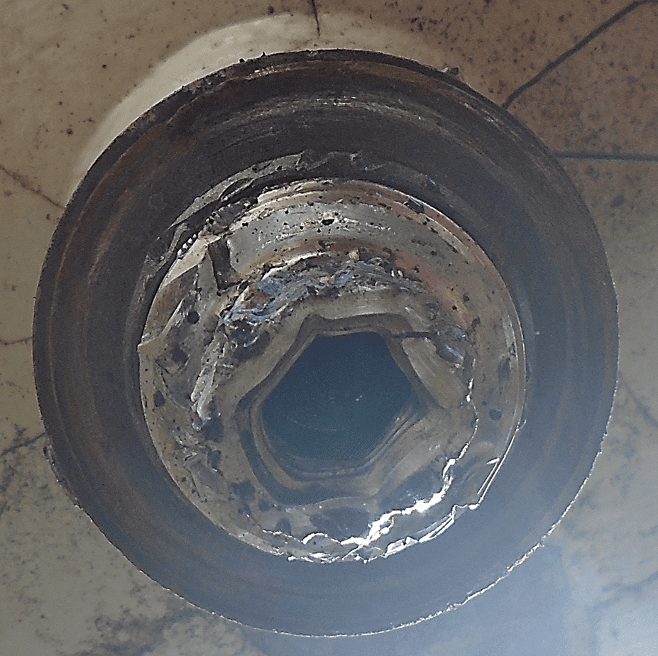
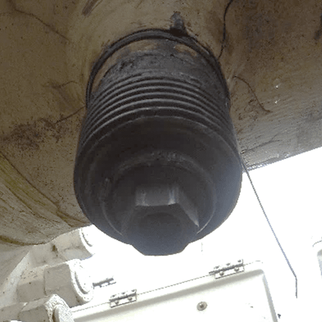
We were requested to service and refurbish a number of access fittings during the platform shutdown. These access fittings were in poor condition and, for some, the historical service history was not known. When servicing the import flowline location the internal carrier plug was found to seized half way in the fitting and attempts to remove (by the previous service company) had resulted in significant damage to the plug (Pic 1). The carrier plug would not have been holding pressure and the only historical isolation on this line was provided by the heavy duty cover. The line could not restart until the issue was rectified.
Solution
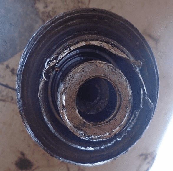
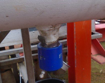
ICR mobilised an on-site machining technician and specialist drilling equipment. The drilling equipment is designed specifically to remove seized carrier plugs from access fittings. It uses a hollow cutter which allows the carrier plug threads to be removed without damaging the internal threads of the access fitting (Pic 2). This allows the remaining plug section to be removed before the internal threads are tapped and a new carrier plug installed.
Results
- ICR were able to remove the seized carrier plug safely without causing any further damage to the access fitting
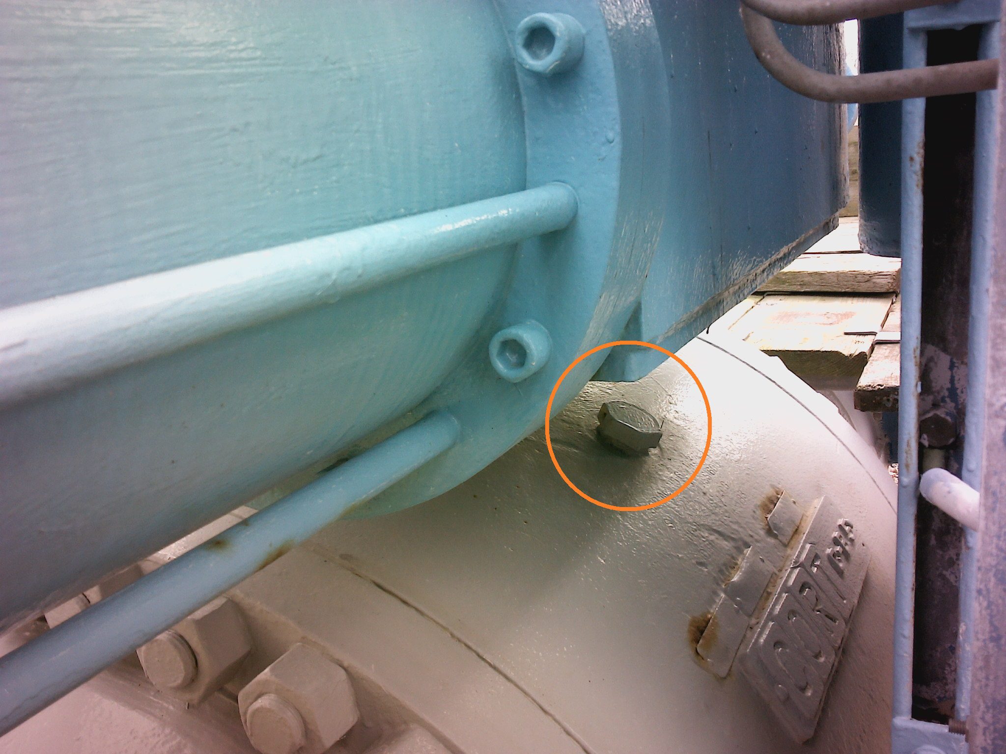
- A new carrier plug was fully installed (Pic 3) along with a new heavy duty cover
- A leak test was then conducted to confirm a seal and that the integrity of the line had been restored (Pic 4)
| Date | Client | Location |
|---|---|---|
| November 2020 | Global Operator | West Africa |
The Issue: Premature mooring chain failures
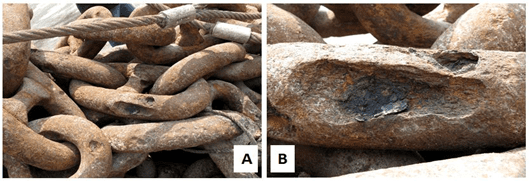
Over the past decade there have been several instances of premature mooring chain replacements due to unexpected failures. On retrieval of the mooring lines, it has been found that the upper chain sections have been significantly affected by the phenomena known as ‘mega pits’ (see Figure 1). This phenomena occurs in tropical waters, and several FPSOs off the coast of West Africa have been particularly badly affected.
The Requirement: Microbiological analysis of samples from an FPSO mooring chain
It was suspected that in these cases, the main corrosion mechanism was microbiologically influenced corrosion (MIC), which then influenced the rate of cracking. Previously, several investigations have been criticised for determining that the root cause was MIC with little, if any, microbiological data to confirm this conclusion. Although MIC is often associated with pitting and unexpected failures in marine environments, it is not the only possible explanation. If further unexpected failures were to be prevented, it was necessary to undertake a microbiological investigation to provide evidence in order to confirm the involvement of MIC.
The Service: Sampling and analysis of samples from retrieved mooring chains
ICR Integrity and NCIMB were asked to undertake the analysis of samples from several mooring chains from an FPSO moored off the coast of West Africa (See Figure 2). This involved writing a procedure to enable a crew member to take samples in an appropriate manner and the provision of a kit to ensure the samples were preserved during transportation to the Oilfield Microbiology laboratory at NCIMB. The sampling kit and procedure were dispatched to the chain retrieval vessel and the samples were taken by a member of the crew from five different depths from a single mooring line once the chain was safely secured on the deck of the retrieval vessel.
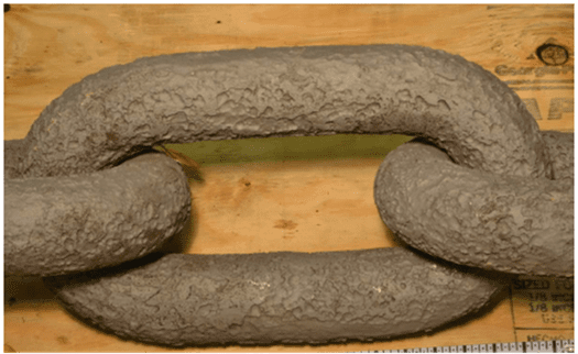
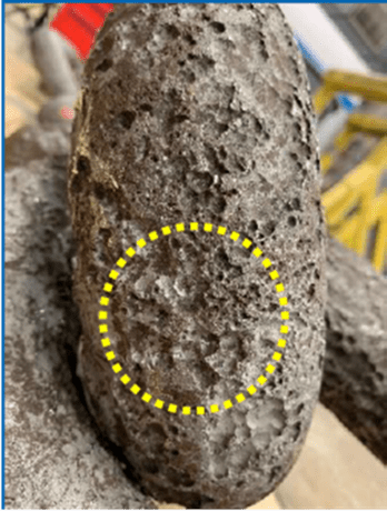
Figure 2: Pitting observed from retrieved mooring chains
| Date | Client | Location |
|---|---|---|
| May 2021 | North Sea FPSO | North Sea |
Scope
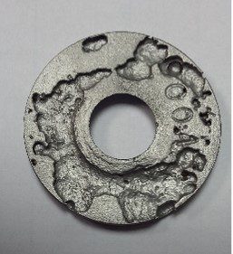
ICR technicians were required to ascertain the level of microbial contamination and activity within an offshore FPSO, North Sea. Microbiologically Influenced Corrosion: Microbiological fouling in oil and gas production systems can result in significant financial loss and plant down-time if not monitored and remediated effectively. Proliferation of sulphate-reducing bacteria (SRB) can cause Microbiologically Influenced Corrosion (MIC) in pipelines and production vessels, reservoir souring and problems with injectivity and Health and Safety issues as hydrogen sulphide is produced.
Solution
ICR technicians were mobilised to the FPSO to conduct a combined corrosion monitoring scope using various microbial techniques to provide a fully comprehensive evaluation. Delivering analysis and information on levels of sessile (attached) from corrosion coupons and planktonic (free floating) bacterial contamination present within oilfield systems and vessels using culture-based methods and DNA sequencing techniques. Thereafter, reporting of data with recommendations regarding microbial control measures (i.e. biociding strategy and monitoring).
Results & Benefits
- Samples were successfully obtained and were backloaded to laboratory facilities for incubation and reading.
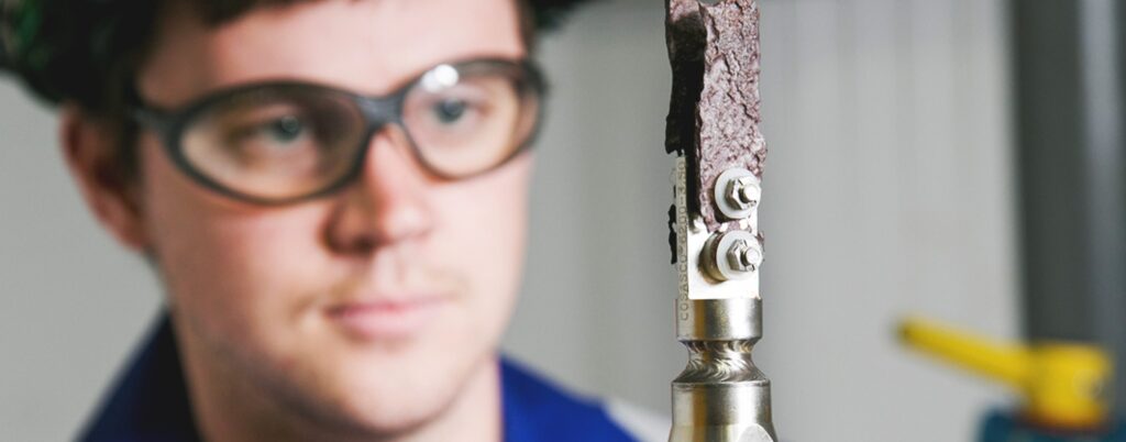
- Microbiological bacteria were accurately detected, identified and quantified using culture-based and molecular microbiology methods; quantitative polymerase chain reaction (qPCR) and 16S metagenomic analysis/Next-generation sequencing (NGS).
- A final report was delivered to the client with recommendations and ongoing support.


Scope
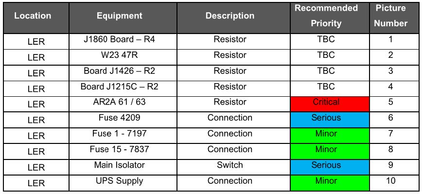
We were requested by an Oil and Gas Operator to conduct a non-intrusive thermal imaging survey on an offshore un-manned platform. The main aim of the workscope was to survey electrical switchboards, distribution boards, control panels, busbars, transformers etc and identify, if any, hotspots that were above the normal operating temperature for the equipment. The risk with electrical components overheating is that they can cause the platform system to trip/shutdown or pose spark potential/fire risk in worse case scenario. The work was carried out while the plant was online using the FLIR T320 thermal imaging camera.
Solution
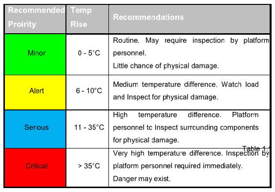
All electrical components noted to have “hot spots” or found to be above ambient or operating temperature were recorded in accordance with the BSRIA standard of LV Electrical Installations FMS 5/99 (see table). During the survey it was noted that several components displayed temperatures significantly above ambient and, potentially, operating temperature.
Results & Benefits
- All results were populated in a table (example left) and rated accordingly using the BSRIA standard. A full report was also issued to the client so they could review the findings and act accordingly.
- Following review of the final report the client was able to arrange repair and replacement of the components. The client believed that the survey was of great value as they would not have been able to identify these issues otherwise. As they were able to rectify the issues it reduced the risk of any unplanned shutdowns and outages caused by faulty electrical components which is of great benefit to unmanned platforms and can provide significant cost saving benefits long term. Routine thermography inspections have now been planned on a yearly basis across all of the clients assets.
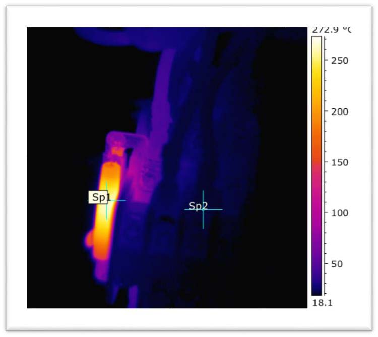
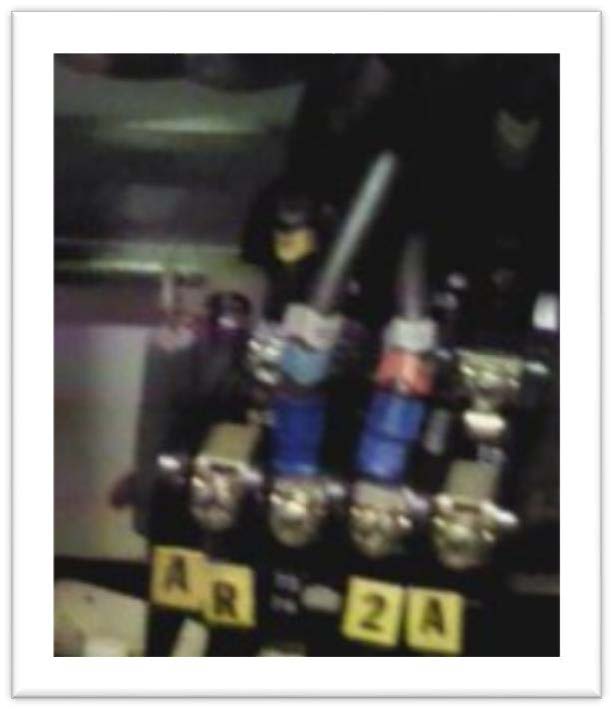
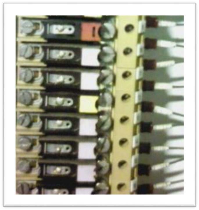
Resistor displaying temperature of 250 degrees which is significantly above ambient and operating temperature. This was classed as a serious priority.
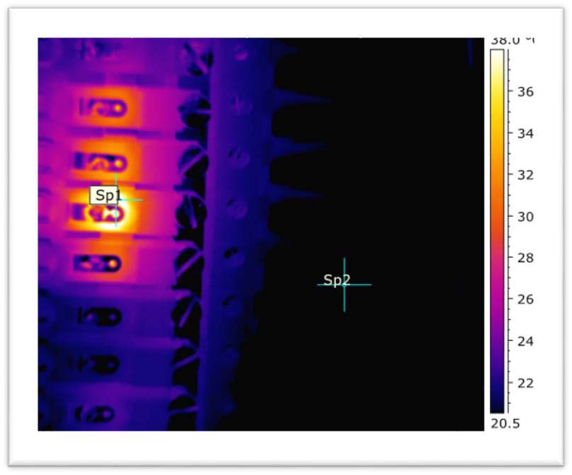
Fuse displaying temperature of 20 degrees above ambient and operating temperature.
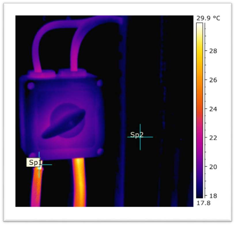
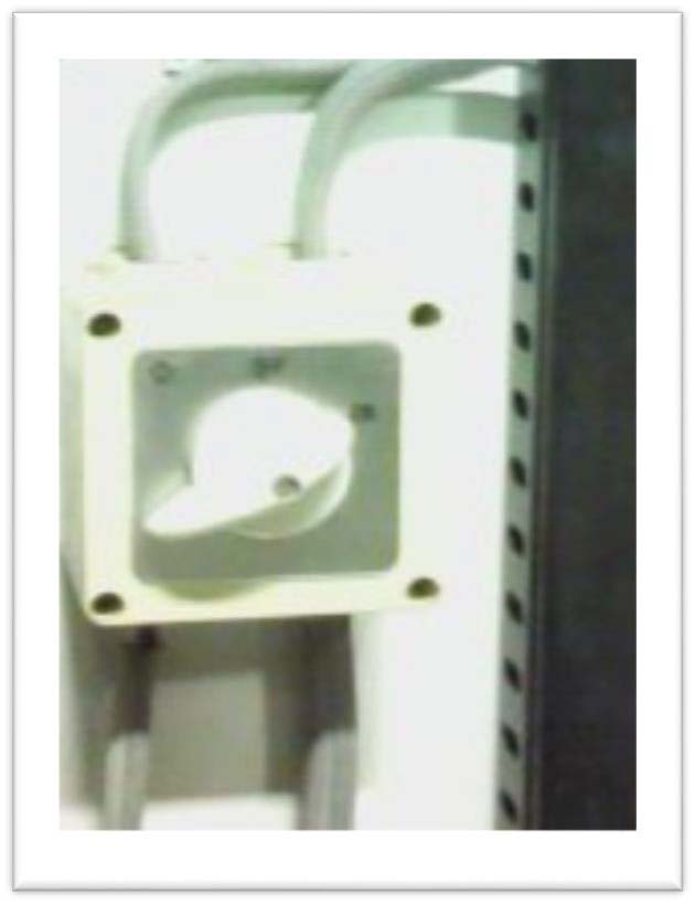
Cables from main isolator switch displaying temperature of 15 degrees above ambient and operating temperature. There is also damage noted to one of the cables.
| Date | Client | Location |
|---|---|---|
| January 2020 | Global Operator | UK Onshore Gas Terminal |
Scope
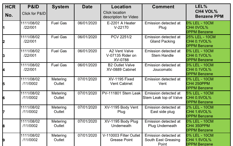
Our client wanted to improve their strategy and planning for detecting and repairing hydrocarbon releases across their gas terminal. Previous surveys had been intermittent with minimal traceability with regards to current releases and repaired releases.
Solution
We proposed quarterly visits to the terminal where all areas would be surveyed by the ICR technician using an FLIR GF320 camera and Inficon Irwin methane detector. Each hydrocarbon release found with the camera would be recorded and tagged, the LEL and Methane quantification (in PPM or %) also noted in order to gauge severity of the release. This is reported to the client in spreadsheet format along with highlighted P&ID’s and video footage.
Results & Benefits
- Using the report the client is able to repair the hydrocarbon releases in order of severity and work through the list.
- During the next quarterly visit ICR would conduct another full survey including all the historical hydrocarbon releases.
- The releases repaired would be removed from the spreadsheet and any new releases found would be added.
- Again all this would be reported to the client. The hydrocarbon release spreadsheet would effectively become a live document for the client to access and would be updated quarterly by ICR.
- Routine surveys like this can offer significant safety and cost saving benefits long term.

Scope
Our client required a non-intrusive inspection method capable of identifying the presence of sand/solid levels believed to be present within a tilt plate separator. The separator was located on an offshore production facility which has been in operation since 1986. The production system present on the facility is capable of processing 31,000 bpd.
Conduct a full thermography survey of the accessible areas of the tilt plate separator and report on the presence and location of any sand/solid build up within the separator.
by identifying the most suitable locations to collect useful inspection footage and collating the findings to obtain an overall sand/solids quantity.
Solution
ICR mobilised an experienced thermographer to conduct the inspection using the latest infrared thermal imaging technology.
The survey was conducted under normal operating conditions. The production fluids within the separator had a temperature of around 60ºC.
Results & Benefits
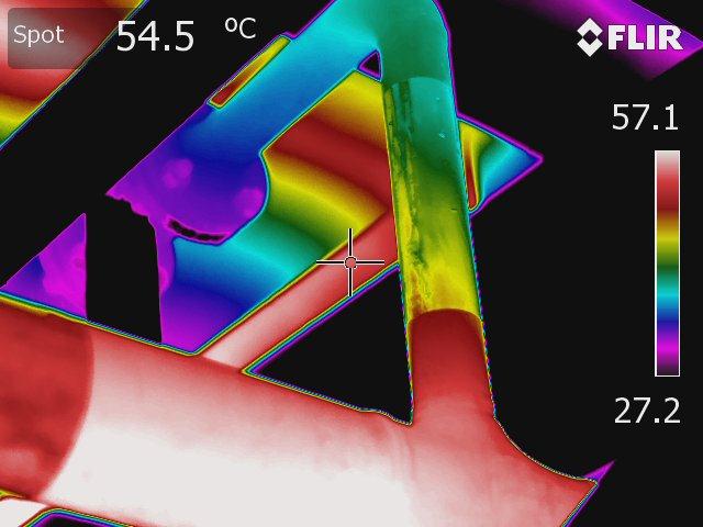
- Sand/solid deposits were visible in the infra-red spectrum due to their insulating effect on the surface temperature of the separator wall. The thermal images captured indicated the presence of significant sand/solid deposits in the lower parts of the separator.
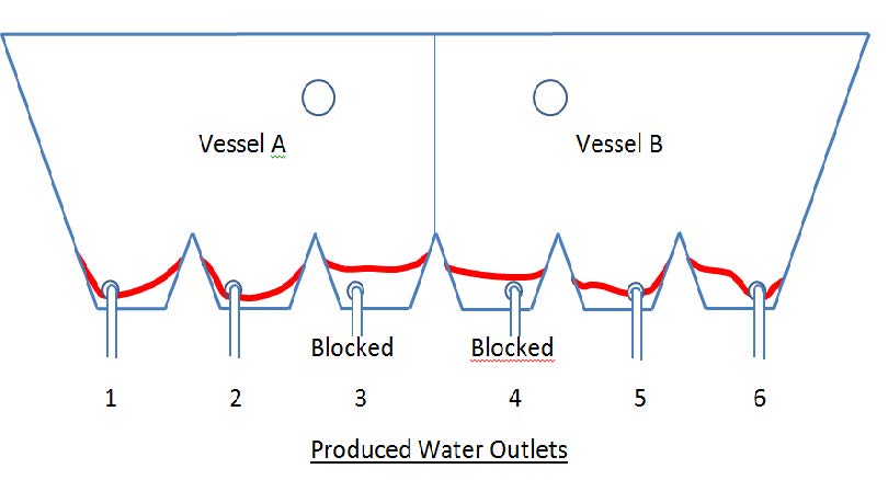
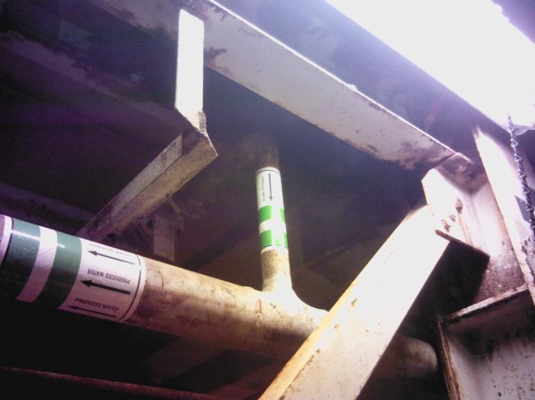
- In addition; during the survey it was found that two of the produced water outlets were partially or fully blocked. ICR suggested that these images be used as a baseline to be referenced during repeat inspections scheduled at regular intervals.
