Date: March 2023
Client: Chemical Supplier
Location: Wales
Client challenge
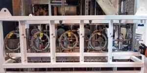
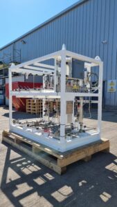
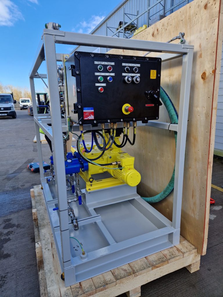
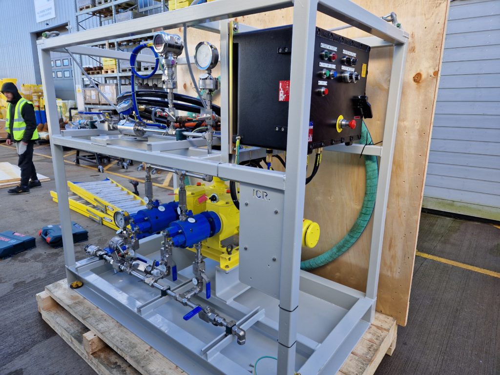
Our client required a Super Drag Reducer Injection Package to handle a chemical with high viscosity which had the potential to impact pump performance. Due to varying process parameters, a solution was needed to automatically adjust injection rates and maintain constant concentration, regardless of flow and pressure variations in the pipeline. The goal was to provide a fully automated system that allowed remote control of pump operations with minimal input required.
The high viscosity (100,000 cP) of the chemical posed a significant challenge in maintaining consistent injection rates as the varying process parameters further complicated the task of ensuring a constant concentration. Our team was asked to design a chemical injection skid with an innovative solution that would automatically adjust the pump stroke length via an Actuator Capacity Controller (ACC). This approach aimed to achieve reliable and automated control of injection rates, enabling automatic pump control remote pump control and ensuring efficient chemical injection.
What we did
To address these specific requirements, our team developed a comprehensive solution encompassing the following key elements:
Automated injection rate adjustment: The design of the chemical injection skid incorporated an Actuator Capacity Controller (ACC) that was capable of automatically adjusting the pump stroke length. This innovative feature allowed for precise control of injection rates, ensuring a constant concentration, regardless of variations in flow and pressure within the pipeline.
Integration of on-skid flow meter and control panel: The ACC was seamlessly tied into an on-skid flow meter and control panel, providing real-time monitoring of flow conditions. This integration facilitated automatic adjustment of injection rates based on the measured flow, ensuring accurate and consistent chemical injection.
Remote pump control: The automated solution enabled remote start and stop functionality for the pumps, allowing the client to control operations remotely without the need for additional input. This feature provided convenience and flexibility in managing the injection process.
Results
The successful implementation of the Super Drag Reducer Injection Package effectively met the challenging requirements posed by the high viscosity of the chemical, enabling efficient and reliable chemical injection. The automated system also allowed for the automatic adjustment of injection rates based on flow conditions, ensuring a constant concentration, regardless of variations in flow and pressure within the pipeline. This provided consistent chemical treatment and optimised performance.
Our client expressed satisfaction with our solution, highlighting its effectiveness, reliability and first-class service and support provided by our team throughout the project.
The Super Drag Reducer Injection Package exemplified our team’s expertise in designing and delivering automated solutions for challenging chemical injection requirements. By incorporating the Actuator Capacity Controller (ACC) and integrating it with on-skid flow monitoring and control systems, we achieved precise and adaptive injection rates, enabling remote pump control and consistent chemical treatment. Our client benefitted from a reliable and efficient solution that not only met their specific needs – but also led to a 60% reduction in power usage (which will increase in the winter) – and received exceptional service and support throughout the project lifecycle.
Client quote:
“To sum up, amazing! We have seen a 30% increase in flow through pipeline at 50 ppm, they do not have to use booster pumps now, and pressure drops across the pipe is reduced. They actually have to gag the flow at the terminals at points because there’s too much! All looking very positive, and the skid pump has been used regularly with no problem. It will be in continuous use today, and tomorrow.”
Client: Major North Sea Operator
Location: UKCS
Client challenge
We were approached by a North Sea Operator to address a chemical injection problem in an Injection Rate Control Device (IRCD) system. The existing multiple valve system on the panel was ineffective, resulting in inconsistent dosing and potential integrity issues. The operator required a long-term solution to ensure accurate and reliable chemical dosing parameters.
What we did
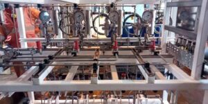
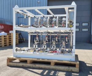
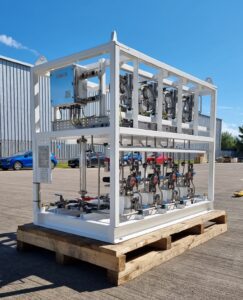
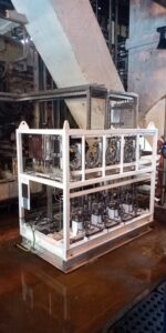
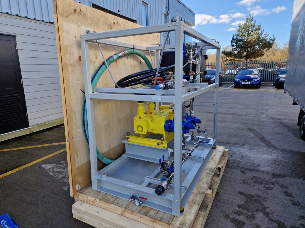
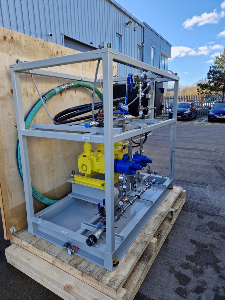
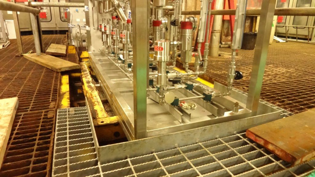
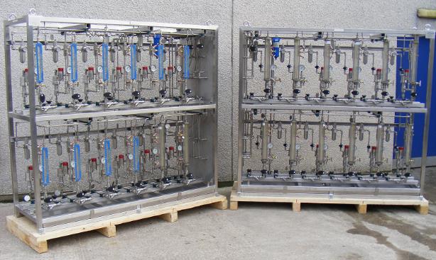
We devised a comprehensive solution by providing a chemical injection system equipped with multiple air-driven metering pumps. Each injection point was allocated a dedicated pump and calibration gauge, ensuring precise and optimal dosing levels. This design also introduced a control mechanism for the overall system, overcoming the limitations of the previous injection package. To accommodate the available space on the platform, the unit was designed as two compact 12-pump rack frames.
Results
The project was successfully delivered within the agreed timeframe. Following the installation of the new system, the injection issues were resolved, and the corrosion/scale inhibition effectiveness was assured throughout the process facilities. The optimised chemical dosing solution provided greater control, accuracy, and reliability, addressing the operator’s concerns and enhancing the overall efficiency of the IRCD system.
Date: May 2022
Client: Major Operator
Location: North Scotland
Client challenge
Our client, a major energy operator, required two Biocide Chemical Injections Pump packages for their oil and gas terminal, as elevated levels of Sulphate Reducing Bacteria had been discovered. This bacteria caused increased corrosion rates on the main pipeline at the terminal, especially in areas with low points where water tends to accumulate. The integrity of the pipeline system was at risk due to this corrosion, necessitating biocide injection at both the pig receiver and the crude oil manifold.
Solution
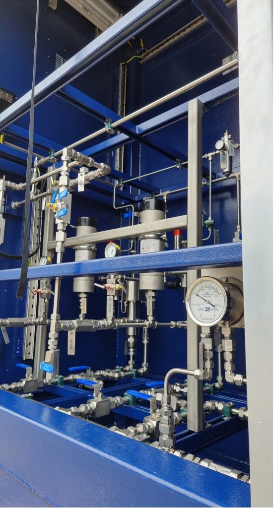
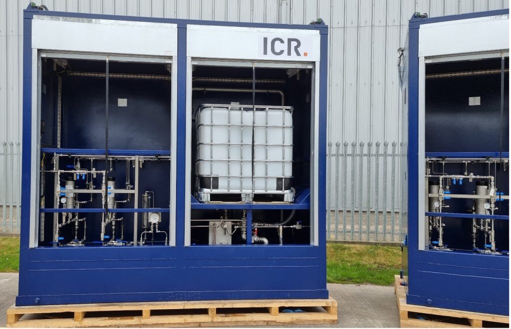
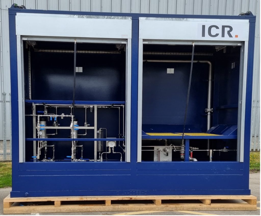
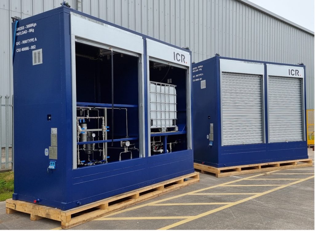
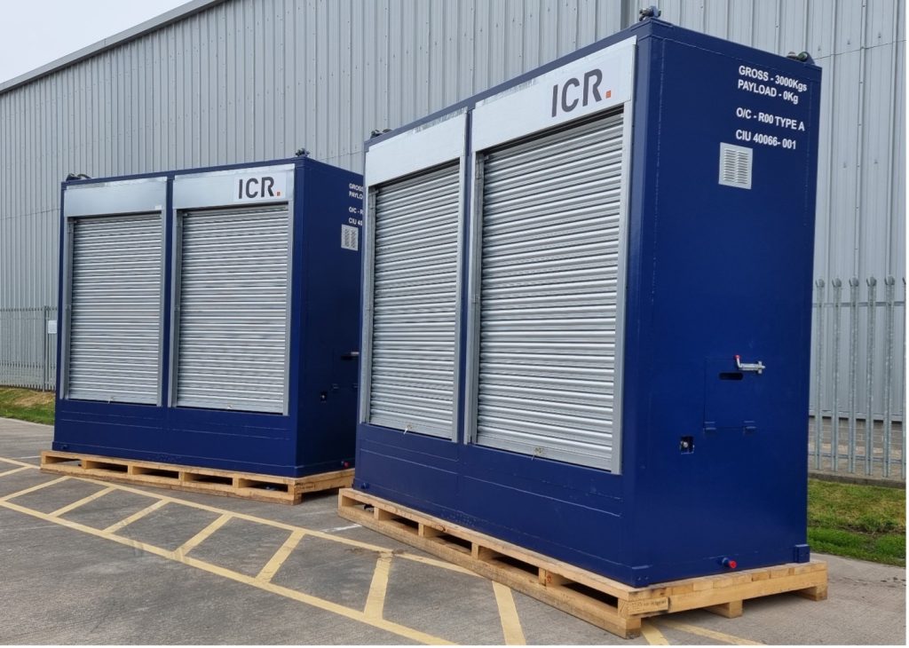
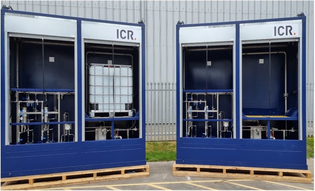
Our team designed and built two bespoke chemical injection units complete with:
- Two CRP2250W600CR-BR Williams Milton Roy Air Driven W Series Plunger Chemical Metering Pumps
- One head operating to individual injection point with one complete standby pump.
All equipment supplied was bespoke and reflected the duty parameters and chemical application specified by our client.
The packages included the following bespoke elements:
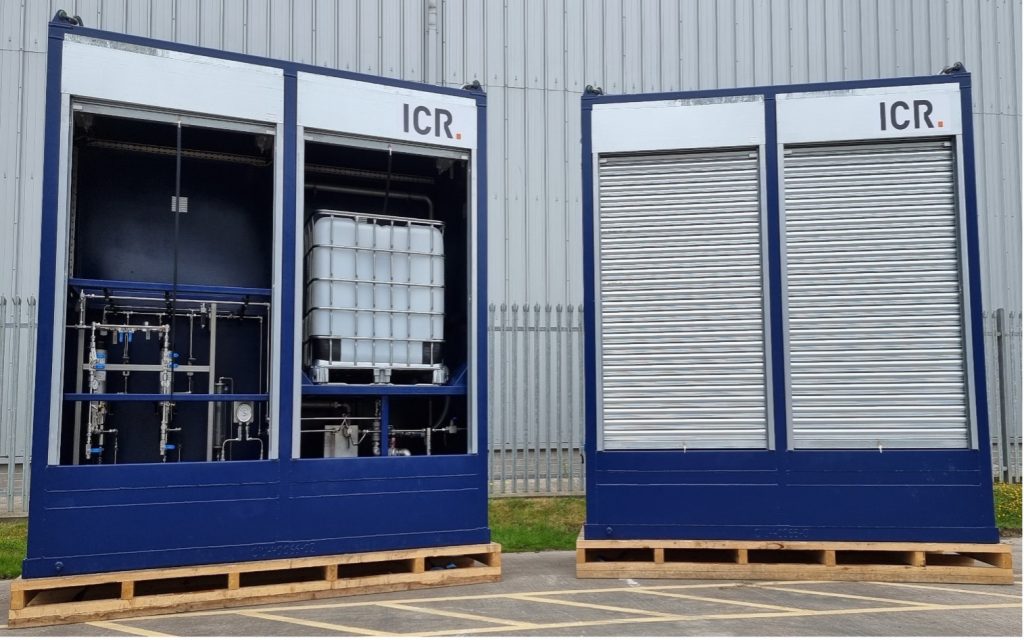
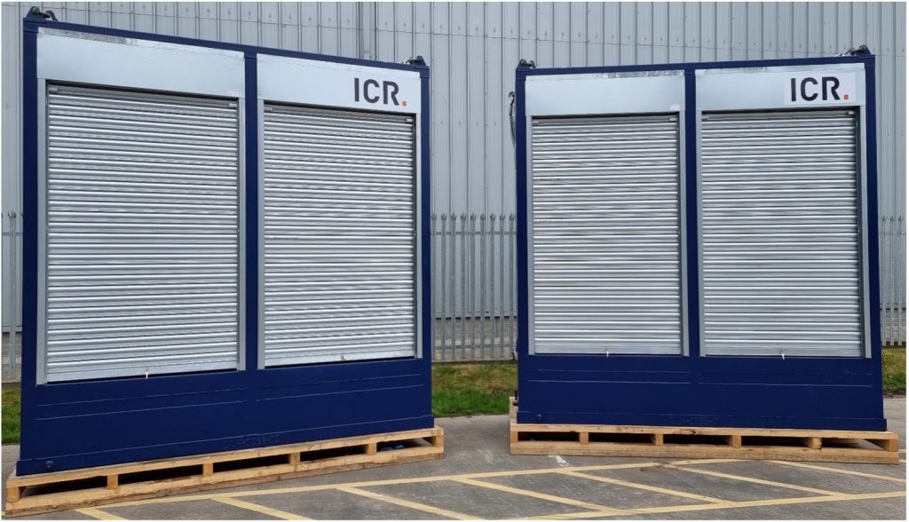
- Two compartment containers divided by a partition wall and painted in accordance with our client’s coating specification.
- Package containerised with galvanised roller doors provided for operator access and designed to ensure safe and easy changeover of IBCs.
- The IBC was connected by a 300mm section of flexible hose and an adapter to fit the IBC outlet connection.
- Each side of the container was internally outfitted with ex-rated fluorescent lighting fittings, controlled by a manual switch which terminated at the package edge.
- Package bunded with two off 1.25m3 bunded sections separated by a bulkhead wall, with flange drain valves.
- Ventilation grills were located on all three walls of the container to avoid ingress of rainwater.
- Equipped with lifting points rated for twice the weight of a fully outfitted container and holding down foot plates with slings and suitably sized and rated shackles supplied to facilitate the single point lift. The containers conform to DNV 2.7-1 lifting and structural requirements.
- Two off M12 earthing was provided and were located on diagonally opposite, external corners of the package.
- The package included safety signage.
All process tubing including, suction, discharge, and air manifolds as well as the fittings and valves were constructed from 316 stainless steel. Instruments had a permanent tag label fitted. The injection pump package was mounted in a 316 stainless steel box frame complete with all valves, instrumentation and piping for safe and proper operation.
Results & benefits
We successfully delivered the chemical injection packages within the planned schedule and under budget. Each package was specifically designed to reflect our client’s specifications, duty parameters and environmental factors.
Date: October 2021
Client: Major North Sea operator
Location: UKCS
Client challenge
Our client, a major North Sea operator, required an Automatic Processing Unit (APU) to remotely adjust injection rates. The unit had to have the following specifications:
- A stainless steel 316 box frame for attaching to a H2S Scavenger rental unit.
- Single vs stroke speed (at 100 stroke length).
What we did
Our team provided an APU that enabled remote adjustment of chemical injection rates from a site control room. The APU received a 4-20mA signal from the control room, and based on this signal, adjusted the stroking speed of the pump proportionally. To control the pump’s stroking speed, the APU utilized a solenoid valve, which was installed locally to the pump in place of the normal Williams Controller. This solenoid valve effectively fulfilled the role of the Controller.
The APU unit offers several advantages, including:
- Remote adjustment of the pump flow rate allowing for quick and easy changeover, especially in a duty/standby setup.
- Remote starting and stopping of pumps enabling remote control of pump operations, enhancing convenience and flexibility.
- Reduction in chemical usage by remotely adjusting the chemical flow rates, the APU assists in reducing chemical consumption.
- Compatibility with site instrumentation as the APU can receive an analog signal from the site DCS or feedback from site or package instrumentation such as flowmeters. This facilitates precise adjustment of chemical injection rates.
- Proportional adjustment of stroke speed as the APU receives a 4-20mA signal and adjusts the pump’s stroke speed accordingly, ensuring accurate control.
The APU controls the stroke speed of the pump by opening and closing a solenoid valve installed locally to the pump, replacing the normal Williams Controller. The solenoid valve effectively performs the role of the Controller, enabling the increase or decrease of the pump’s stroke speed.
The table below provides an example that demonstrates the relationship between the analog signal sent to the APU and the resulting stroke speed or pump volume. It’s important to note that stroke speeds and volumes may vary depending on the specific pump models used.
| Signal | Strokes per Minute | Litres per hour |
|---|---|---|
| 4mA | 0 | 0 |
| 6mA | Pump A – 8.75 | 84 |
| 8mA | Pump A – 17.5 | 168 |
| 10mA | Pump A – 26.25 | 252 |
| 12mA | Pump A – 325 | 336 |
| 14mA | Pump A 35 & Pump B 8.75 | 420 |
| 16mA | Pump A 35 & Pump B 17.5 | 504 |
| 18mA | Pump A 35 & Pump B 26.25 | 588 |
| 20mA | Pump A – 35 & Pump B 35 | 672 |
Results
By successfully implementing the APU, our solution allowed our client to remotely adjust injection rates, control pump operations, and optimise chemical usage. The APU’s flexibility and compatibility with various instrumentation make it a valuable tool in enhancing operational efficiency and ensuring accurate control in critical processes.
Scope
ICR was approached by the client to replace their existing ferric sulphate injection package. The current pumps were oversized for the process requirements resulting in high pulsation and vibration due to the short stroke and fast motor frequency required to meet the flow needs. ICR conducted an engineering site survey, working closely with the client to find the best solution.
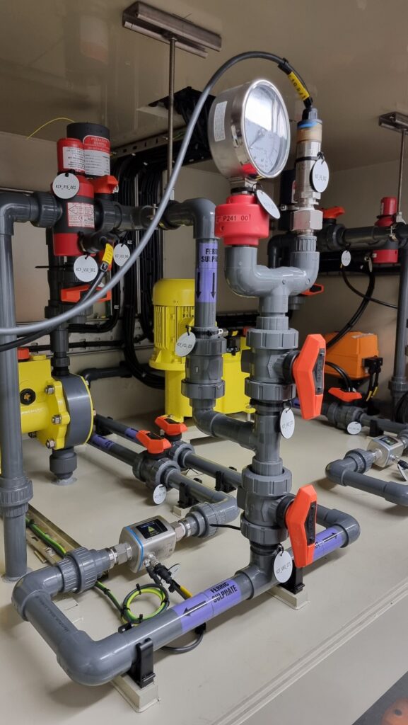
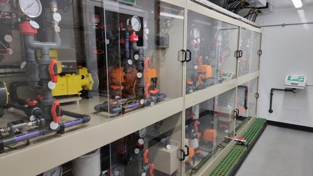
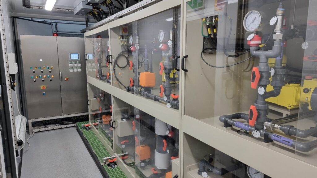
ICR delivered a fully automated, containerised ferric sulphate injection package consisting of 6 electric drive, VFD controlled injection pumps (4 duty and 2 standby).
Solution
Ferric Sulphate Injection Package consisting of the following:
- Fully automated ferric sulphate injection package, with required hardware to allow remote monitoring, control and operation via onsite control system
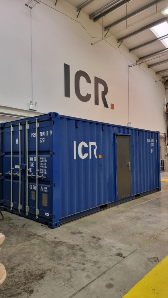
- Package integrated into modified 20-foot shipping container, housing all chemical injection, electrical, and ancillary equipment.
- Container internals lined out with 12mm thick “Aqua-panels”, chemical resistant non-slip floor and integral stainless-steel bund
- 3 Polypropylene injection pump cabinets (2 duty and 1 standby) c/w Perspex sliding doors
- Each cabinet contains 2 Milton Roy MAXROY, VFD controlled, electrically driven pumps with each pump being capable of injecting 407.5 litres per hour
- Package control panel with integral HMI touch screen and local VFD touch pads
- Emergency eye bath station
Results & Benefits
- Fully assembled package delivered to site, minimising hook-up and onsite work requirements
- Bespoke package designed to meet client specifications and process parameters
- Fully automated to be integrated into on-site control systems
Scope
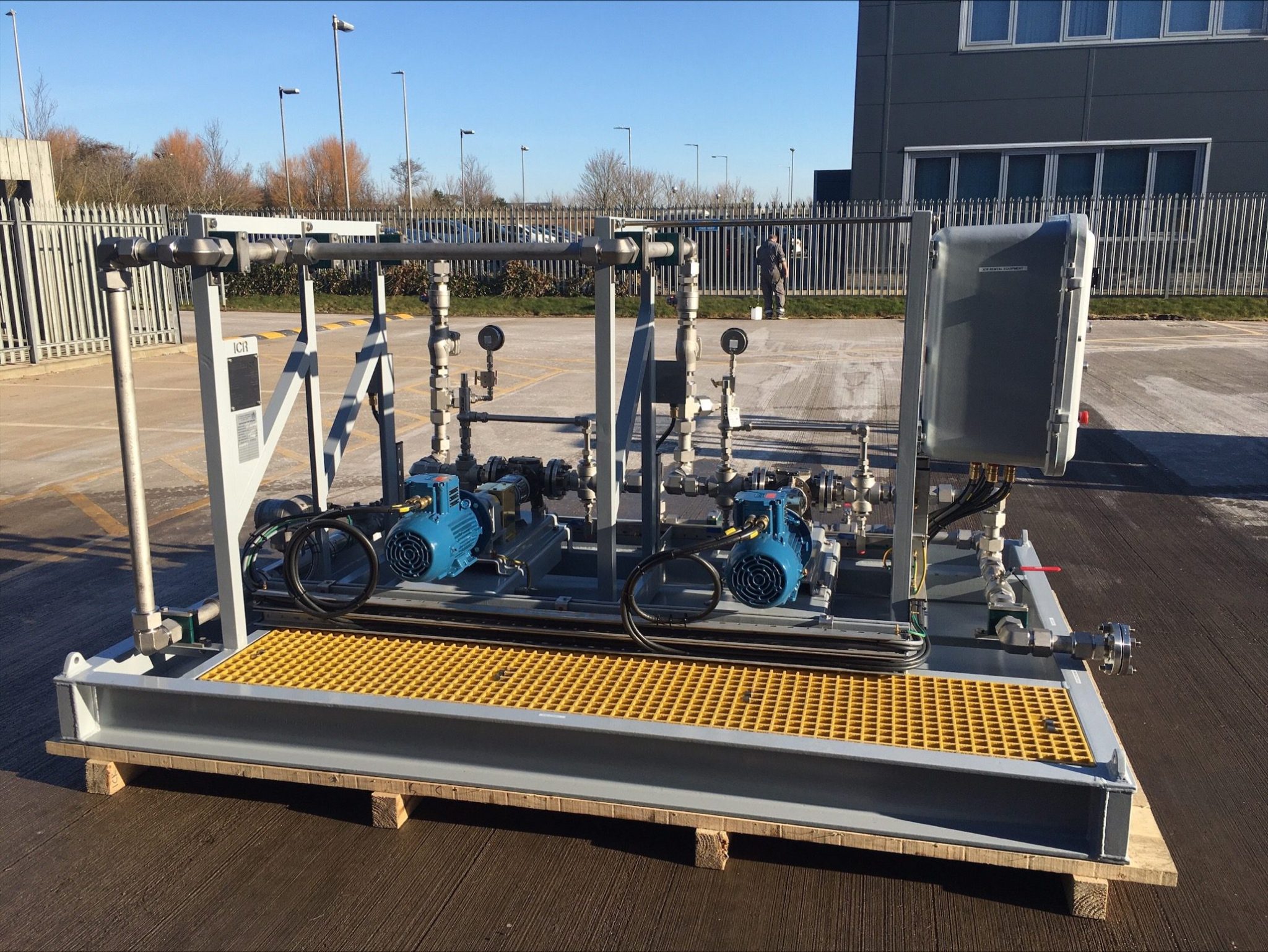
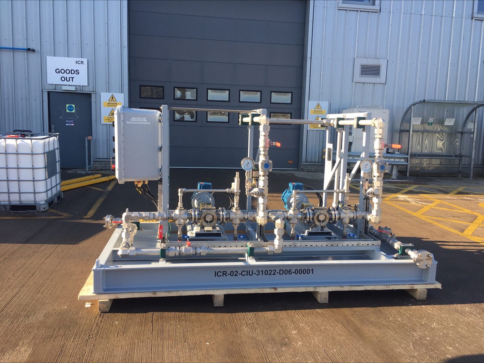
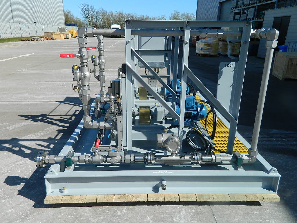
To supply an electric drive Pour Point Depressant injection package. Injection Rate: 0-1800 litres per hour Duty Process Pressure: 13.8 barg Fluid Viscosity: Up to 600 cP Ambient Temperature: -15 to +30 °C Skid ATEX Classification: Zone 2 IIA T3 Power Requirement: 440V 3ph 50hz Chemical reservoir: Tanker (by others)
Required Injection Rate: 0-1800 litres per hour
Duty Process Pressure: 13.8 barg
Fluid Viscosity: Up to 600 cP
Ambient Temperature: -15°C to 30°C
Skid ATEX Classification: Zone 2 IIA T3
Power Requirement: 440V 3ph 50hz
Chemical reservoir: Tanker (by others)
Solution
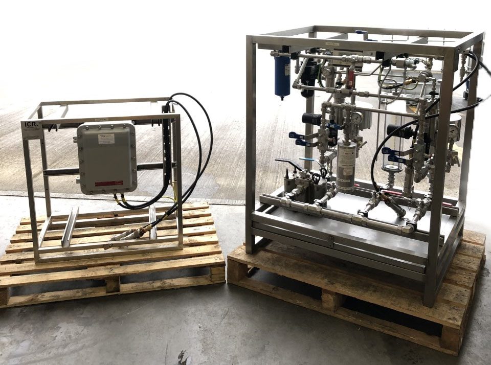
- ICR proposed SPX Flow Internal Gear Pumps in a duty/standby arrangement c/w variable speed electric motors
- Motor speed was locally controlled by a skid-mounted Ex d control panel
- Coriolis Flowmeter power supplied via the control panel
- On-skid equipment earthing provided along with On-skid cable support system
- Package was installed on a painted carbon-steel base frame c/w integral sloping drop tray with drain valve, certified lifting points, sling set and spreader lift beam
- Tubing, fittings, valves and components supplied in 316 stainless steel
- Discharge manifold fitted with dissimilar check valves for increased reliability
Results & Benefits
- Pumps capable of pumping viscous fluids at the required flowrate
- Bespoke control system configured to accept incoming power from client distribution board Overpressure safety built into design with discharge pressure relief valves
- Stable discharge flow and pressure through use of pulsation dampeners
- Real time flow rates and cumulative flow displayed locally on Coriolis flowmeter
Scope
ICR was approached by a major North Sea operator to design and manufacture a bespoke, permanent Injection Pump Package for dosing of Sodium Hypochlorite to four seawater lift pump caissons on a UKCS Platform.
Solution
ICR supplied a package with 4‐off air driven, API-675 dosing pumps for Sodium Hypochlorite dosing to respective seawater lift pump caissons. Each pump was served by a dedicated Solenoid Valve (SOV) to start / stop pump on signal from platform Integrated Control and Safety System (ICSS).
The package included a back‐pressure control valve on each pump discharge line to prevent syphoning of the sodium hypochlorite solution from existing hypochlorite storage tank.
The package comprised of the following:
- 1 of painted carbon steel base frame c/w titanium drip tray
- 4 off (4 off duty) Williams Milton Roy CRLD200-TI-TFE air driven hydraulic actuated diaphragm chemical injection pumps
- Process tubing, fittings, and wetted metallic parts supplied in Grade 2 Titanium.
- Suction manifold incorporating all valves, suction filter for each pump and common calibration pot
- Discharge lines for each pump incorporating a pressure relief valve (PRV) routed to pump suction, pressure indicator, back pressure control valve and isolation valve
- Air manifold incorporating isolation valves, filters, and regulator
- Pneumatic installation on the package incorporating 4‐off SOVs (each supplied with manual override) on each pump supply (for individual pump start/stop control)
- Instrument junction box, located at skid edge to facilitate connection of client cabling
Results & Benefits
- Fully assembled package delivered to site, minimising hook-up, and onsite work requirements
- Bespoke package designed, built and fully tested to meet client specifications and process parameters.
